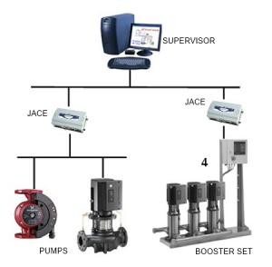
ontGenibus driver is used for monitoring and controlling Grundfos pumps utilizing GENIbus.
GENIbus (the Grundfos Electronics Network Intercommunications bus) is a fieldbus developed and maintained by Grundfos to meet the need for data transfer in all typical Grundfos motor/pump applications. In the field of Building Management, control of Water Purifying Plants, Water Works and Industry applications etc. Grundfos devices with GENIbus can be wired together in networks and integrated in Niagara systems
COMMUNICATION MEDIUM
GENIbus is based on the RS485 hardware standard, therefore, standard RS485 limitations apply, e.g. max. 1200 meters / 32 devices etc.
RS485 comms settings are fixed as follows:
Baud Rate : 9600 bits/s
Data Bits : 8
Parity : None
Stop Bits : 1
REQUIREMENTS
Availability of GENIbus on Grundfos pumps : Not all Grundfos pumps are equipped with a Genibus port. This is true even for some of the variable-speed pumps. Often a Genibus add-on module needs to be ordered with the pumps. This is usually a very reasonably priced add-on.
On the other hand, a CIU module (for converting GENIbus to another open protocol such as Bacnet or modbus) is *not* required when using this driver.
Pump addressing : The pumps need to be assigned addresses. This is typically done by Grundfos technicians using their portable R100 tool.
Twin Pumps : In some twin-pump Grundfos solutions, the two pumps use the Genibus for internal communication. When operating these pumps via ontGenibus driver, you must bring them into Single Pump Mode (with R100) and handle them as single pumps to avoid creating a multi master network. Therefore, all automatic switch-over and similar logic will need to be configured in Niagara.
LOCAL/REMOTE MODE
To control a pump over GENIbus, it must first be brought into Remote Mode by use of the REMOTE Command (A BooleanWritable Local/Remote point type is provided in the driver for this purpose). As long as the pump is regularly addressed from the bus it remains in Remote Mode. If it is not addressed for 6 seconds, it automatically switches back into Local Mode. The basic poll scheme in the Niagara driver framework normally ensures that this criteria is satisfied, as the normal poll rate is set to 5 seconds by default. However, there could be exceptional circumstances when it is not. For example, if none of the proxy points are linked to logic and none have alarm or history extensions and none is being currently viewed either in workbench or in a PxView, then the driver will not be polling any points.
DISCOVERED POINTS
Clicking the discover button in the PointManager view will always bring up the same list of points regardless of the type of pump. The GENIbus protocol doesn't really provide a method of discovering available points. The discovered points pane, therefore, lists commonly available points on most Grundfos pumps. All may not be applicable to every pump. One can either check the Grundfos documentation specific to the particular pump or, simply try it to see if it retrieves data without falling into fault status.
Similarly, further points may be available in some pumps, other then the ones listed on the discovery pane. These can be added manually. However, the NEW button on the point manager will not work. Instead, use the following procedure:
- Read Grundfos documentation to determine class and idCode of the data item you want to add.
Class 2 : Measured Data
Class 4 : Configuration Parameter
Class 5 : Reference Value
Class 7 : ASCII-string - In the discovered pane, take any point of the same class and add that.
- Open the properties of the added point and adjust the idCode under ReadParameters of the proxy extension.
- Remember to rename the point
PUMP-TYPE SPECIFIC GRUNDFOS DOCUMENTATION
Grundfos has published detailed documents describing readable/writable points, modes of operation etc for individual pump types. These documents are titled "Operating the ...Pump via GENIbus or G100". If you want detailed information, please request these documents specific to your pump from the local Grundfos office.
AUTOMATIC SCALING OF RAW DATA
Many proxy points will automatically retrieve not only the current raw value, but also unit and scaling information automatically from the Grundfos pump via Genibus. For such proxy points, the linear conversion and unit properties of the proxyExtension will be automatically set. You should not need to modify these.
SOME COMMONLY USED POINTS
Monitoring
- operation_mode : Actual operation mode (Start/Stop/Min/Max)
- control_mode : Effective control mode (constantPressure, proportionalPressure, constantFrequency,automaticSetpoint)
- sys_ref : Control loop reference (Effective setpoint). The pump may return this either as an absolute value with a unit, or as a percentage. Converting from percentage to actual units can require logic to be configured according to the pumps documentation)
- speed : Motor speed in rpm
- h : Head feedback in pump applications
- q : Flow measurement in pumps applications
- f_act : Actual frequency in Hz or percent
- t_e : Electronic board temperature
- t_m : Frequency convertor module temperature
- t_w : water temperature
- i_m : Motor current
- p : Power (W)
Alarms
- led_contr_red : status of the red LED on pump. In case of alarm, this is either ON or FLASHING.
- alarm_code : Current alarm code (if any)
- alarm_log_1...5 : the code for the 5 last occurred alarms (1 is newest, 5 is oldest)
Control
- RemoteLocal : To control a pump over GENIbus, this point must be used to command the pump to REMOTE mode.
- StartStop : a boolean proxy point to start/stop the pump. If it is necessary to issue not only start/stop but also MIN and MAX commands, the enumWritable proxy point named "OperationMode" should be used instead.
- ref_rem : writable reference (setpoint) in remote mode. Avoid using this proxy point as it is not an absolute reference.

